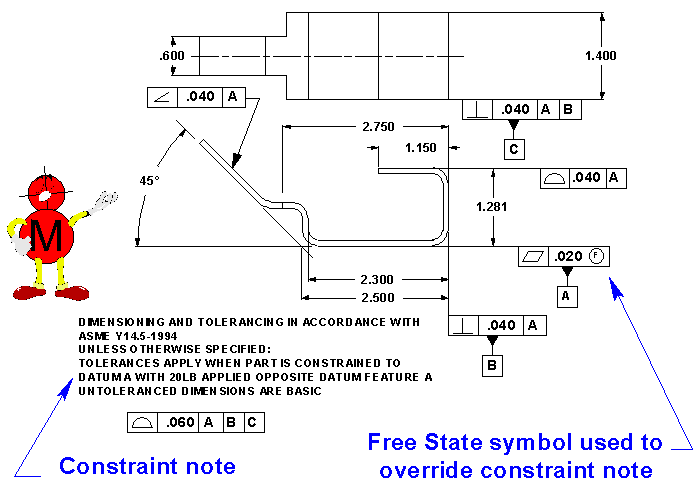
The left figure shows the drawing callout.
How to note flatness sheet metal drawings.
Unless you need the part to have a flatness that is better than the sheet metal gauge tolerance.
Minimum bend reliefs allowed.
After you insert the bend table in the drawing bend tags are added to the selected drawing view automatically.
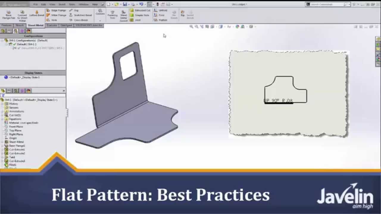
The flat pattern drawing doesn t always list these factors.
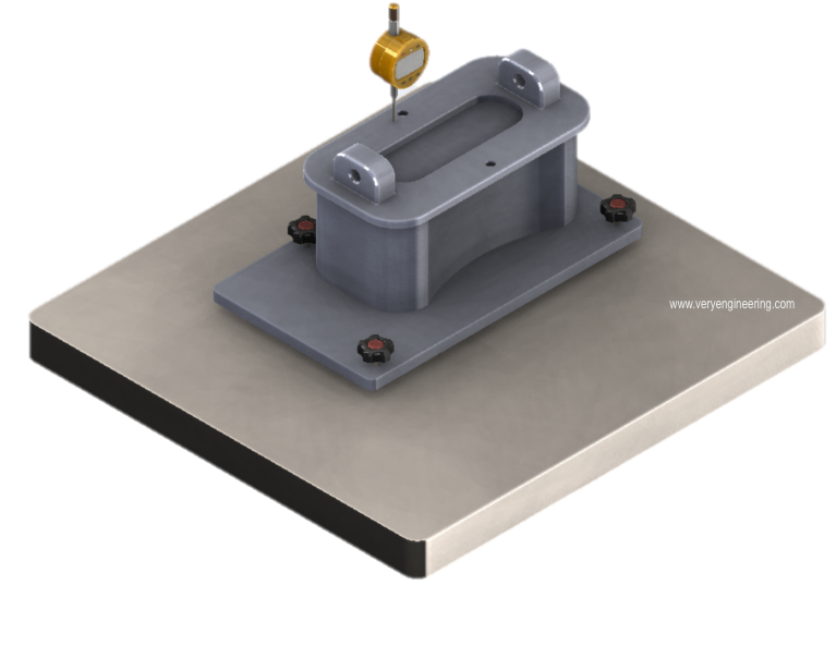
The flatness control c defines how much a surface on a real part may vary from the ideal flat plane.
Toggling the visibility of sheet metal bend notes.
To control the bow try using straightness applied to your sheet metal gauge thickness feature of size.
I want stress relief radii.
It is a common symbol that references how flat a surface is regardless of any other datums or features.
Gd t flatness is very straight forward.
No mmc or lmc applicable.
Flat pattern drawing views can display bend line notes or bend tables.
Toggling the visibility of bend lines.
For door panels front panels interior panels and racks see document 10 1006 for information on adding a note regarding the implementation eps 121.
Flatness is a form control.
To put a flatness on sheet metal part will be hard to control because of the stock sheet metal gauge size tolerances are relatively nice and tight.
I am apply my dimensions carefully so that they are unambiguous.
The flatness control c defines how much a part s surface may deviate from its perfect flat form.
Bending factors affect the flat pattern.
The boxed symbols can be read this surface must lie between two parallel planes spaced 0 2 apart in all views the right figure shows a possible actual part condition.
Perfect flatness is when all points of a surface lie in the same plane.
Although notes on each drawing will differ the first note on all sheet metal drawings that contain bends should be as follows.
I don t put any standard notes on my sheet metal drawings.
Yes new in 2009 drawing callout.
Note that the flatness tolerance must be less than the size tolerance associated with the surface.
It comes in useful if a feature is to be defined on a drawing that needs to be uniformly flat without tightening any other dimensions on the drawing.
Dimensions given on a flat pattern are affected by several bending factors like k factor and bend radius during the 3d modeling stage.
I systematrically specify bend radii on my drawings and i include details showing what the bend corners look like before bending.
Bend tags are formatted by the dimension style and do not have a leader by default.
I have read up on and taken a course on the asme y14 5m 1994.
Toggling the visibility of bend region lines.
Creating drawings of flat patterns.